Friday, August 31, 2018

Having the task to know what to do with this layout has hung heavy on me. Money never came into it. What had been spent on the layout meant nothing because it gave Darren something to wake up for everyday. As the horrible disease destroyed his body, His mind was still as sharp as ever.

I wanted the layout to continue to mean something to someone. I wanted whoever had it, that they would know what it meant to Darren and they would also cherish it.

There really was only one person to gift this layout to. He is a mini Darren. His love for trains reminded Darren of when he was his age. He was the only person Darren trusted to be in the layout room without Darren also being there. They talk over the internet about all things trains. whenever his dad was coming to visit he would be there as well, politely asking if he could go into the layout room.  Daren would speak so highly of this wonderful young man.

When I asked his Dad if I could give the layout to Dillon, I am so grateful that he said yes.

Darren's dream will continue to be cherished. I could not ask for a better home for it.

Thank you Dillon, I know Darren would be so honored that you as the next generation Train enthusiast have his dream to help you grow.

RIP my beautiful Husband , you left us all way to soon.

Tuesday, August 21, 2018

Last night about 10.10 pm Darren left us. he fought MND to the very end. it was quick, and peaceful. and totally unexpected. we knew MND was in his lungs BUT he was laughing with the carers and I than said he could not breath. He Died in Gosford Hospital.

I just want to add. that yesterday at about 12 midday . Dazza and Paul finished the laying of track, even across the door. it would have meant he could have run trains all the way around. the Top level was complete.

to Darren it was not the running of a train that drove him, it was the building of his dream.

Tuesday, July 10, 2018

Gunnedah's Last Control Panel Completed

This is quite a large milestone, having the final control panel completed, this one controlling all of the points in the main Gunnedah yard section of the layout.

This now means that all points on the layout are operated from the control panels, with route selection clearly visible.

The completion of these panels also means that as far as wiring goes, all major electrical work on the top deck is now complete, which in itself is another major milestone.

The four control panels still need to be mounted properly, which will be done next, but having them plugged in and operational is a huge reward for what has been a considerable amount of work.

Cheers
Darren


Tuesday, July 3, 2018

Panel Number Three Completed

Panel number three, which controls the four sets of points for Anbeon yard, as well as the two oil sidings on the main line heading into Gunnedah, has been completed.

Once again I am very pleased with how the panels have turned out, the LED equipped buttons are super bright making route selection extremely clear.

Anbeon yard features two sets of points forming a crossover, and on the panel these two sets of points are operated simultaneously. If the single LED button in the centre of the crossover is pressed both sets of points change and that button is illuminated, and to set the points back to the straight ahead position, either of the two LED buttons for the straight ahead route can be pressed, with both LED buttons lighting up and the points changing to the straight ahead position. This is definitely a nice little feature of this method of point control.

The final panel to be completed is for the main Gunnedah yard section, this panel contains thirty-seven of the LED buttons, so will be by far the most time-consuming, but no doubt the most visually rewarding once completed.

Cheers
Darren


Saturday, June 30, 2018

Panel Number Two Completed

Panel number two has now been completed and temporarily mounted to make sure it is working as it should, which it all did first go.

As with the first panel I am exceptionally happy with how this one has turned out.

The next panel will feature eleven of the LED equipped pushbuttons, so should look even better again.

Cheers
Darren


Thursday, June 21, 2018

The First Point Control Panel Completed

The last few weeks have been spent working on getting the point control panels underway. There will be four of these panels located around the layout, and together they will control the thirty-three sets of points on the upper deck of the layout.

The first step of the process involved using a piece of black corflute and some masking tape, which although looking quite ugly, allowed us to get an idea on what kind of spacing was needed for the actual LED equipped buttons to be installed without interfering with each other.

Initially I had tossed up the idea of using some form of thin masking or pin striping tape that would be used to represent the track plan on the various panels, but this would be difficult to do precisely, as well as being incredibly fiddly at best.

I then remembered that Officeworks have a print and copy service, where you can get quite large plans or posters printed. Looking at the website revealed that they do printing on a self-adhesive material, and an A0 sized (841 x 1189mm) poster cost a mere $34.00.

Knowing that the largest panel I needed was just over one meter long, the other panels being much shorter, and each panel being only 160mm high, meant that I would be able to fit all four panels onto one sheet. All I had to do was design the panels.

I have used a program called Empire Express Basic to draw the track plans that I have previously used on this blog, and whilst this would not give me the end result I needed, it would give me the ability to do a basic design that would at least have everything looking even and consistent in style.

After doing the initial track plan for the main Gunnedah panel, it was a matter of transferring this design to my photo editing program (Gimp), where I was able to fatten up the lines, manipulate the overall size to fit the panel dimensions, and invert the image from white with black lines to black with white lines.

After the main Gunnedah panel design was completed, I then used various sections to make up the other three panels (basically copying and pasting), this way the design of each panel was consistent.

After all of the line work was completed, it was time to notate the panels, identifying the various sidings, and at each end of the panel identifying where the line was either coming from or going to.

After notating the main panel, I printed it out (as black lines on white so as not to use all of my printer ink) on normal paper, and we stuck it to a test piece of 3mm MDF to see how it looked, and to check button spacing before getting the final designs printed.

This initial print showed that the font size could probably be reduced by about 30%, and I also wasn't completely happy with the font I had chosen. So after spending some time going through a lot of different fonts, I finally found one that I was happy with, and so another test print was done.

Along with change of font, I did some massaging of track plans before the final designs were ready to print. However, before doing the final print on the adhesive material, I had the panel designs printed out on normal paper at Officeworks, which on the same sized A0 sheet was only $8.95. I did is to make sure that the size that it printed was exactly as I needed it to be, and I am pleased to say that it was, and so the final copy was ordered, which basically involves uploading the image to the Officeworks website, and it was ready to pick up the next afternoon, a better service you couldn't hope for.

My wife went to our local Bumnings, and was able to get some sheets of 1200x600x3mm MDF cut down to 1200x160mm, which means that we only needed to cut them to length, which we can measure directly off the printed panel designs.

We started with the smallest panel first which is to control the points for the colliery branch and the two sidings, as this only contains four buttons and is the shortest of the panels.

The other difference with this panel is that the point control circuit board is located about three metres away, mainly because at around $80.00 each it was financially beneficial to run these buttons from the point control circuit board located near the abattoir siding.

As each button has three control wires, and there are four buttons, that makes twelve wires that need to be run about three metres, so I needed to find a way to do this as neatly as possible. Using Cat 5 network cable would have been nice, but it only contains eight wires so that's no good, and then I hit on the idea of using ribbon cable.

Once again looking to eBay, you can buy approximately ten feet or three metres of forty wire ribbon cable for about $9.00 delivered.

The ribbon cable has ten different coloured wires which simply repeat in the same order, so separating twelve wires from the forty wire strip, gave us four sets of three wires with a unique colour code. It was then just a matter of cutting the plugs of end of the button leads and soldering the leads to the ribbon cable. I have ordered some plugs so that the panel can be unplugged from the ribbon cable for easy removal, but they have yet to arrive so that's a small job still to be done.

Once the MDF panel was measured and cut to length, it was given a light coating of satin black apply from a spray can, this helps to seal the MDF as well as making the edges look much neater.

The next step was to cut the panel diagram from the self-adhesive sheet. This was then carefully lined up, and with the backing material peeled away pressed onto the MDF panel.

The next step was to mark out where each button would be located, and then using a six millimetre hole punch, a circle of the adhesive material was easily removed, so that when the drill was used it wouldn't catch on the material and potentially rip or damage it in some way.

The next step was to drill a seven millimetre hole for each button, and then the little bezel that surrounds the bottom can be pushed into the hole and locked into place.

The panel is then flipped over, the buttons lined up in the hole and screwed into place with the small screws that they come with.

It was then time to temporarily locate the panel in place on the front edge of the module, and at the other end of the ribbon cable, plug it into the point switching board. With the point control bus wiring switched on, two of the four buttons lit up as they should, and pressing the other unlit buttons made the correct set of points move in the correct direction. There's nothing quite like being methodical with your wiring, and having everything work as it should the first time.

Even though this is only a small panel, I'm very pleased with the way it turned out, and once in place with the facia panels on either side it should look even better.

The green LED's within the buttons are very bright, and make route selection very clear, and I cannot wait to get the rest of the panels completed.

Cheers
Darren


Friday, May 11, 2018

475 Days


475 days ago the first length of curved track and single set of points (highlighted in green in the first picture) on the corner module leading into the main Gunnedah yard section was permanently laid and operational.

475 days later the last pieces of track, the extension of the grain silo road (closest to the backdrop) and the locomotive service roads (between the grain silo road and main line curving off to the right) on the corner module (highlighted in green in the second picture) at the opposite end of the main Gunnedah yard, have been laid and are operational.

This means that apart from the lift-out section that will go across the doorway and link to the proposed helix, all of the track, and points (31) on the layout proper are permanently in place and operational.

Whilst there is still lots to do on the layout, this is an exciting milestone to have finally reached, especially given the circumstances under which the layout has been constructed.

Cheers
Darren


Saturday, April 28, 2018

Anbeon Track and Points, Plugs and Magnets


Work continues to progress at a steady rate, the last couple of weeks 
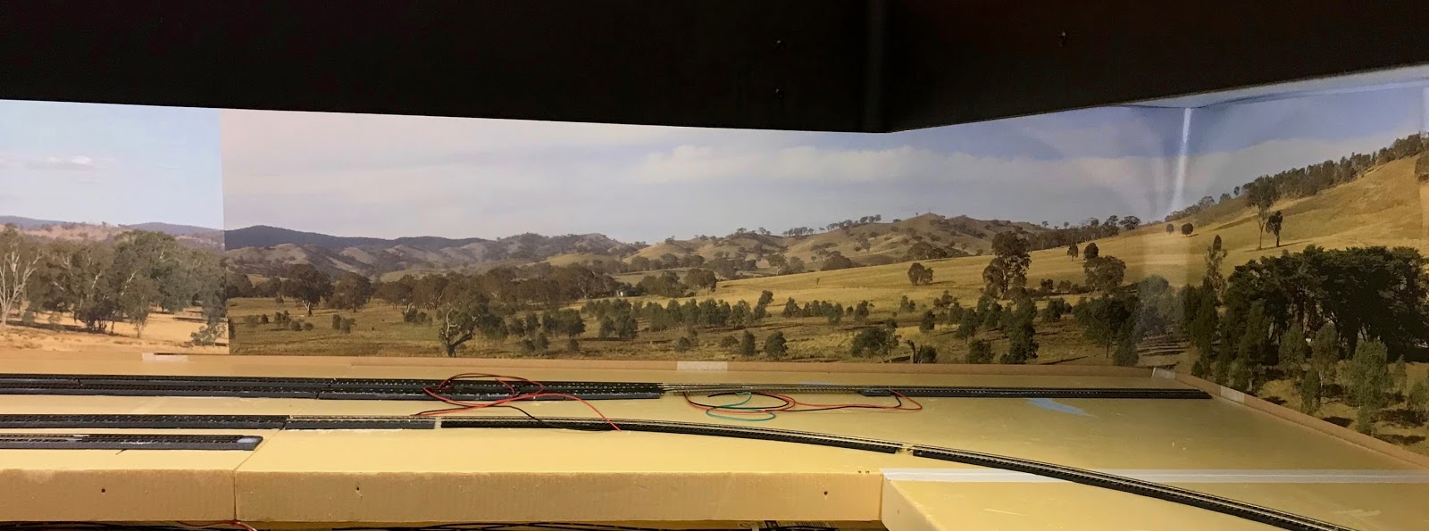
seeing the extension of the yard at what is now known as “Anbeon” completed. The extension of the yard trackwork on this corner module (highlighted in green) consists of a single set of points with about 450mm of track either side, so nothing overly complicated.

This corner module already contained the curved track and first set of points for  Gunnedah’s main yard, so it was only a matter of adding the extra track and set of points, and then flipping the module over and joining the new dropper wires to the existing bus wiring.

 All of the points on the upper deck level of the layout are equipped with Cobalt IP Analogue point motors, made by DCC Concepts, and the point motors are controlled by Alpha Switch A boards, also made by DCC Concepts. Each board has six outputs, and each output has the capacity to control two point motors, so you can control six individual points or up to six pairs of points.

Driving tw0 point motors simultaneous with the press of one button is handy where you have two sets of points forming a crossover, where you will always change both points at the same time. The buttons used with the boards are a very small and neat pushbutton design equipped with an LED, with two buttons controlling a single set of points, or three buttons when you have two sets of points forming a crossover. So making a control panel with the track diagram, the buttons are placed on the diverging side of the points, so when selected the appropriate LED lights up indicating route selection. This is a very effective system that is very simple to set up as it is literally a plug and play system.

Whilst there doesn’t seem to be a limitation within reason of how far away the points can be from the control board (I have tested to a distance of about three metres), as I am using a modular style of construction, there are a couple of places on the layout where the control panel and control board will be mounted on one module, and one or more sets of points operated from this panel are located on an adjoining module. Because of this the wiring between the control board and point motor cannot be continuous, so a method of easily disconnecting the wiring between modules needed to be found.

After doing a fair bit of looking around it appeared that a suitable style of plug would be a four pin style that is commonly used to power the small cooling fans inside your typical PC. Looking on eBay, I found that you can buy twenty centimetre leads with a female and male plug on opposite ends, with fifteen of these costing nine dollars $9.00 including delivery.


With each point motor controlled by only two wires, each plug can therefore handle joining two sets of points on an adjoining module. Using them is very simple, we simply cut each lead in half, strip the insulation off the end of each wire, strip the insulation from the wires coming from the control board, twist the wires together, add a dab of solder and then slide some heat shrink over each joint. The point wiring is then permanently attached on the underside of each module, with the male and female plug sticking out about five centimetres from the corners of the adjoining modules. This is enough so the plugs can be easily plugged and unplugged, and once plugged together can be tucked back under the modules.

When the point control panels are made with the point motor boards attached to them, I also want them to be easily disconnected from each module, so there needs to be a plug to disconnect the boards from the three wire power bus that runs around the layout framework specifically for the point control boards, and another plug to disconnect them from the wires going to each point motor.

The control boards have screw terminals for the main power (three wires) and point activation wires (twelve wires), but the idea of unscrewing up to fifteen wires to remove the boards is crazy, so again I spent time looking for appropriate plugs.

For the three wire main power plug, I ended up using the same style of plug used on remote control servos, and again these can be bought as short extension leads with a male and female plug on each end, and if you are willing to wait a couple of weeks for delivery, they can be bought as cheaply as $2.99 for ten leads including delivery!


Once again these leads are simply cut in half, one half is soldered to the main bus wiring running around the room, the other end attached to the three screw terminals on the control board. This provides another neat and tidy connection that is very easy to unplug when needed.

That then leaves the actual point control wires that need to be able to be disconnected when the control panels are removed, with up to twelve wires needing to be disconnected this time. After looking around I came across what seemed to be commonly referred to as D-Sub connectors, which are available in a few different styles, but the ones I chose have screw terminals for fifteen wires, and a male or female fifteen pin plug (DB15).


These are a more expensive style of plug costing around $9.00 each (eighteen dollars $18 for a male and female set), but they are well suited to my needs. The wiring from the control board is run to one plug with all wiring being colour-coded for identification and tagged where necessary, and the other plug is located on the appropriate module with the wires from each screw terminal going to the appropriate point of motor/motors.

As these plugs are bigger and heavier, and sit on the underside of the modules, I wanted a way of securing them to the underside of the module, but still make them easy to access and to pull forward so they can easily be plugged and unplugged. After deciding that most styles of clips or hooks would be too cumbersome, I hit on the idea of using magnets.

I had purchased ten Neodymium block magnets (19mm x 10mm x 1.5mm) some time ago, primarily to experiment using them as uncoupling magnets, but figured if one was glued to the underside of each plug, and then in the appropriate position on the underside of each module, four magnetic flathead screws are screwed into the foam module, the plug is quite firmly held in place, and yet can be easily slid forward to be plugged and unplugged, and then pushed back where the magnet once again firmly attaches the plug to the screws.


I find that it is definitely worth thinking outside the square, and looking to other hobbies and forms of technology to find solutions to our model railway problems.

Cheers
Darren


Saturday, April 14, 2018

The Final Main Module Completed


The past few weeks work has seen a bit of a milestone reached, that being track and points laid and operational on the last module to be completed (highlighted in green), which means that for the first time, apart from the lift-out section across the doorway, trains can and have been run completely around the room.

Looking back, construction of the layout began on the 15th of February 2016, so a little over two years has passed to get to this point. Trains could have been running a lot sooner, but it would have been at the expense of finishing off the backdrops, sky panels, fascia panels and the LED lighting, all of which were quite large jobs that took time to complete. However, it is a decision I do not regret making as even though there is no scenery as yet, having the trains running in front of a proper backdrop under proper lighting as soon as each section is completed looks so much better than it would without them. That, and I feel that if some of these jobs were not done in the beginning, day they may not end up getting done at all, as once trains are running it can be difficult to get the motivation to do these more difficult jobs.

This module we have just completed has both the main line leading into Gunnedah, which has to two sidings coming off it, one representing the BP oil siding and the other the Vacuum (Mobil) oil siding, which are located towards the front section of the module, and at the rear of the module is what loosely represents Emerald Hill, which is where trains end up after running through Gunnedah and out the other side.

So whilst the main line into Gunnedah with the two oil sidings and the loose representation of Emerald Hill are both located on this module, they are in effect on completely different sides of Gunnedah. Doing it this way makes the layout operationally far better, as trains travel a much greater distance around the layout going to and from their destinations.

As the Emerald Hill section of this module bares little resemblance to the real thing, and the fact that it is a terminus rather than a through station, I’ve been thinking that it really should be called something else, and something fictional. So last night whilst pondering this subject it hit me, why not call this station/yard  “Anbeon” (Or possibly “Anbeyon”).

As the title of this blog is “Gunnedah and Beyond”, if you slur your words together slightly, “and beyond” quite naturally morphs into “Anbeon”. So, it seemed logical enough to adopt this name for this station/yard section, and quite honestly, does it sound any stranger than other actual names like Awaba, Attunga, Oberon, Oolong, Elong Elong, Illabo, Kinalung or Uardry!

Part of the Anbeon yard continues on to the corner module, and I’ve made a slight modification from previous plans, so instead of two sidings with dead ends, I have added a set of points and brought these two sidings together forming a runaround, which will make this section far better operationally, as well as probably being more prototypically correct.

Yet again I am very happy with the neatness of the wiring underneath the module. I’m also happy to report that using the cable ties, leaving the tag about 30mm long, giving it a slight smear of glue and inserting the tag into the baseboard foam, once dry forms an amazingly strong bond, and requires a surprising amount of strength to pull the tag out of the foam, far exceeding what the weight of the wiring would ever amount to.

Whilst not located on the most recently completed module, I’ve included a couple of photographs of a sort of mixed goods train sitting in what will be the colliery siding, just because I’m sure most people like looking at actual trains.

Cheers
Darren


-->

Saturday, March 17, 2018

March Module Madness - Two More Almost Completed

-->
Since the last update, we have just about completed the two modules situated on the opposite side of the room to the main Gunnedah yard section, both are highlighted in green on the track diagram images.

The middle module contains the two colliery siding tracks, as well as the two main line tracks, and also has the set of points where the abattoir siding branches off what I am commonly calling the “Beyond Gunnedah” main line.

 The last module contains the two main lines as well as the abattoir siding, which features a pair of points that form the runaround located directly in front where the abattoir building will be located, and the length of track at the end is where the cattle yard section of the abattoir is located.

Refridgerated wagons can be dropped off or picked up by trains in either direction and will be shunted into position in front of the abattoir building, and cattle wagons are also able to be dropped off or picked up by trains travelling in either direction, but with more difficulty depending on whether refridgerated wagons are present in front of the abattoir building.

As the two main lines approach the end of the last module they make a turn towards the front of the module, and this is where they will join the lift out/lift up/swing away/magically appear section across the doorway, that will also link to the proposed helix joining the top and bottom deck of the layout.

With any form of removable section of a layout, there is always the possibility of trains being run off the edge of the layout, resulting in a usually catastrophic trip to the ground 4-5 feet below. Because of this I have implemented a way of cutting off power to the last section of track by using insulating rail joiners and installing a pair of micro switches between the dropper wires and the main bus wires. In practice I only need to use one micro switch on either the black or red bus wiring, but as I have not decided exactly how or where they will be mounted, having two connected gives me some extra flexibility, so it’s worthwhile having both connected at this point.

There is nothing radically different to what has been done before, so lots of thought is still given to where track droppers can be located to make the wiring underneath as simple and neat as possible. Two of the attached photographs show underneath and above the end module from either end, so you can see that whilst the track is somewhat spread across the module, by careful placement of droppers the underneath wiring is kept quite central and neat.

However, in a slight departure I am trying another way of locating the wiring in place. I am still using cable ties to both keep the wires neat and tidily grouped together, but unlike before where the long tail of the cable tie has had glue put on it, and then a section of masking tape laid across it, this time the tail of the cable tie is cut to about 35-40 mm long, a very fine jewellers screwdriver is used to drive a very thin slot into the foam board, the tail of the cable tie is smeared with the same liquid nails style glue we use for the track and underlay, and the tail of the cable tie is inserted into the slot.

The tail of the cable tie needs to be firmly pushed into the slot which is merely a guide, and the foam grips the cable tie tail quite tightly, with the glue giving the extra strength needed. Testing so far has shown this to be very effective, with the added benefit of looking extremely neat. However, if need be it requires very little effort to remove the cable tie from the foam if any alterations need to be made to the wiring.

For me, one of the enjoyable parts of building this layout is the thought process involved in every facet, be it the bench work, track laying, wiring etc, and the evolution of the way in which things are done. There are things we are doing now that I wish I had thought of in the beginning, but it’s often not until you have actually done something that you come up with a better way of doing it, that goes for not only model trains, but life in general, old head on young shoulders basically!

Cheers
Darren