Friday, December 22, 2017

MERRY CHRISTMAS

-->
It’s hard to believe another year has just about gone by, and more than likely for most people it has not been without its challenges, nonetheless, I hope that at this time of year a little bit of Christmas spirit touches everybody, and a very Merry Christmas is had by all.

My wife was very determined that we were going to have a very “Christmasy” Christmas this year, and has gone all out with the decorations. We are fortunate to have a nice sized back room that is just perfect for decorating, and decorated it certainly is.

The main feature (as far as I’m concerned haha) is the “Christmas Express”, which you can see in the video, chuffing its way through the snow covered winter wonderland.

Upon completion of this highly detailed, prototypically accurate, fine scale, miniature representation of the real thing, my wife and daughter questioned me as to why my layout is taking so long, when they have gotten this up and running and finished in only a couple of hours, clearly they are much better at this model railway caper than I am!

Best wishes to everybody over the holiday period, take care, be safe, and hopefully we will all get something a little railway related under the Christmas tree, and even if some of you steam buffs have been a little naughty, even a piece of coal won’t go astray haha……

Cheers
Darren


Sunday, November 19, 2017

Light Engine Movements at Gunnedah


Last weekend I had a surprise visit from some old friends, some of which I have  known since my first year of high school in 1984, our common interest has always been the old Rotary powered Mazda’s. Back in the day these were plentiful and cheap, and with some simple modifications went very very well indeed, now they are not so plentiful, and commanding some very very big dollars. But what does this have to do with model railways?

One of my mates brought along his son who is very much into model railways, and while his main interest has been in steam era British railways, he also has a keen interest in the New South Wales railways, especially the electric passenger trains and the early diesel rail cars like the 620-720 sets.

So after a couple of hours standing around ogling our old Mazda’s and talking all things car related, everybody headed off except my mate and his son, so it was time to adjourn to the train shed and start talking all things model railways.

It was also a chance to turn on the layout lights and fire up the DCC system, and give some trains a run through the mostly completed Gunnedah yard track work.

I only had 4875 sitting on the operating track work, but after running it back and forth a few times, it was soon joined by 42201, 6041, and my 624-724 set that I don’t think has been out of the box since getting it in August 2008, apart from once when I first bought my NCE Power Cab in 2009 and sat it on a single length of flex track to change it from the short to the long address.

It was a thoroughly enjoyable couple of hours chatting about trains, and for me watching trains actually being run back and forth through Gunnedah yard, which is probably about an eight meter run or thereabouts with what track is down at the moment.

It's great to get trains running to test out the track work, to make sure that everything is running smoothly before any ballasting or scenery begins, so I was very thankful to have somebody keen and interested to do this for me.

A few videos were taken on the iPad of the light engine movements, a couple I have uploaded.

As an aside, I definitely need to get to the Haskel back scene behind Gunnedah, as it has started to lift, so will need some glueing back down at some point.


Saturday, August 26, 2017

Meatworks Research


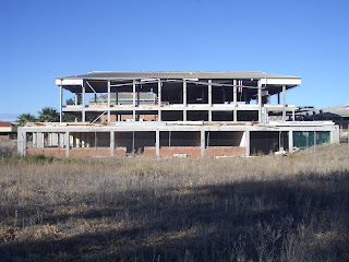
As a bit of an addendum to the previous update, I remembered a particular abattoir that I had seen pictures of, that was almost the perfect example of what I am trying to find for Gunnedah.

The abattoir in particular is the MacLaucghlin Meatworks, which was in use for an amazingly short period of time, built in 1938 and closing during 1942.

There is a detailed write-up on the NSW Railways Infrastructure and Operations blog site, as well as a great collection of extremely detailed photographs, a couple of which I have reproduce w, mainly to show what a great subject for a model this particular abattoir would make.


I also came across some other rather stunning pictures of this abattoir  that I thought   worthy of sharing.

From the Facebook page "Explored Visions by GD" https://www.facebook.com/exploredvisions/?hc_ref=ARSDNdcTEBFVdAa4kQYV-W0BIhScjHCYOdLCcihnj0bMtR0MHBv_7T1CpyJ8RaqyTM8&fref=nf


  And probably my favourite photograph is this one found on Flickr, https://www.flickr.com/photos/billilingra/14709023816/in/photolist-orB3Pq-opMAjU-orBfLS-orRcmt/ 


Tuesday, August 22, 2017

Searching Wide & Far for an Abattoir for Gunnedah

--> Whilst the “Beyond” part of the layout is some way from completion, there is always a need to be looking ahead so that when the time comes I am at least organised to a certain extent.

One of the challenges with any layout is finding appropriate buildings be they stations, goods sheds, residential housing or industrial buildings. For those that model British, European or American railways/railroads, there are quite a few manufacturers that cater for the various styles of buildings found in these locations, however for those modelling Australian locations, the availability is not so great, especially when it comes to the more out of the ordinary buildings.

And (yes I’m starting a sentence with a conjunction but apparently it’s okay) so it is with Gunnedah and its sizeable abattoir located on its own siding as the main line continues northwards. From the information and pictures I have gathered, modelling the Gunnedah abattoir to scale would require a massive amount of space as it is a sizeable piece of industry, so it is a matter of finding something that fits with the scale of the layout, but still has that “abattoir” look about it, or is at least something that when you are told this is the abattoir, your mind quite happily accepts that it indeed “looks” like an abattoir.

To some extent it is kind of lucky that there is no real specific look to an abattoir, they tend to be not particularly architectural, don’t really follow any particular style or even size, which definitely makes the job of finding something appropriate somewhat easier, but not totally.

As part of my research into finding a suitable building to represent the abattoir, apart from looking at the real thing, I have also looked at other layouts that feature an abattoir of some sort to see what they have used for ideas and inspiration. One of the best looking abattoir complexes I have seen is located on Ray Pilgrims high-quality NSWGR based layout Bylong (http://bylong.blogspot.com.au/ ), which features a collection of structures that make up the abattoir buildings, as well as an adjoining cattle yard. I have borrowed a couple of photos from Rays  blog site to illustrate how good it looks. I’m not sure if this is modelled on a particular location or building type, but in its setting is perfectly believable as an abattoir.

American company Walthers are prolific manufacturer of railway related products, and have a large variety of industrial style buildings, however none of the ones I have seen looked to be totally suitable for use as an Australian style abattoir. Casting my search a little wider I came across a website specialising in HO scale structures, one in particular catching my eye as something that maybe suitable.

The website is http://www.custommodelrailroads.com/judysjamsandjellies-HO.aspx and the actual structure is called Judys Jams and Jellies. What I initially liked about this building is that it appears to feature a red brick and concrete main structure, which whilst not identical, is not massively dissimilar to the actual abattoir at Gunnedah if you squint really hard. Photographs of Gunnedah abattoir were given to me some years ago by Marcus Ammann who also has a spectacular NSWGR based layout The Main North, http://mainnorth.blogspot.com.au/

The other appealing factor of this building is the footprint, at 16.5” long x 5” deep x 9.75” high (including roof details) or 419mm x 127mm x 248mm for those metrically minded. When we did a rough layout of the abattoir siding the other week (which will be in a forthcoming blog post) I had placed the track roughly a tissue box width from the back scene, which is somewhere around 4.75”, so this structure at around 5” deep would suit perfectly well.

Being slightly more picky, it would be good if the platform side of the building did not have a section at the end which juts out, effectively cutting down the length of the loading platform (which will need to be extended anyway to the whole length of the building), and if it was 50% longer overall it would be even better, but, as an off the shelf proposition it is definitely one of the better ones I have seen so far.

Being a kit will obviously cause some challenges, my daughter however is very accomplished at building some of the more complicated Lego kits, so I wonder if with a bit of patience making the step to styrene model railway kits is not too much of a stretch!

In the meantime I will continue to search and see what other structures may be useful for Gunnedah’s abattoir, and I also welcome any suggestions that anybody might have for structures that will fit the scene, ideally around 5” deep and anywhere up to 36” long will do the job nicely.

Cheers
Darren


Monday, July 31, 2017

Proposed Gunnedah And Beyond Track Plan and Operation Overview

-->
This is not really a progress update, more of an “overall vision” of what I am hoping will be achieved over the coming months.

As far as the main Gunnedah yard is concerned, 90% of the track is in place, all of the points are working, and trains (well, a 48-class on light engine duty) can be run from one end of the yard to the other. The next challenge is to be able to run a train completely around the room.

The layout was always designed to operate with two levels, the top level comprising Gunnedah Yard with representations of what is found on the line both on the way into Gunnedah and out the other side. The priority however, is to get the top level as complete as possible first.

The track plan shown is pretty much what I would like to get down to allow continuous running as well as some “trip trains” that will allow for some actual operation.

Starting with the proposed helix (that may or may not eventuate depending on circumstances), that would bring trains from the lower level which is effectively “staging” and representing trains coming from Werris Creek/Newcastle/Sydney, to the top level, joining the single line running around the inside of the layout which represents traveling towards Gunnedah.

This line continues around the room and has two sidings located on the approach to Gunnedah. The first siding is the BP oil siding, the second is the Vacuum (Mobil) oil siding. The BP siding is shunted by trains heading to Gunnedah, where empty tankers will be pulled from the siding and full tankers (having come from Werris Creek/Newcastle/Sydney) placed in the siding. Empty tankers will then dropped off in Gunnedah Yard, and will then await being added to a return train.

The second siding is the Vacuum siding, this was typically shunted by trains heading back from Gunnedah towards Werris Creek, full tankers would have been left in Gunnedah Yard and attached to trains heading back towards Werris Creek, and again empty tankers pulled from the siding and replaced with full tankers.

Both of these operations will typically involve a mixed goods consist, and allow for some simple shunting duties by shunting the sidings, as well as placing empty and full tankers within Gunnedah Yard.

Gunnedah Yard itself has a few sidings, the main grain siding with silo, another oil siding, and at the far end of the yard will be a stock siding. In reality the stock sidings are slightly further along the main line, however space kind of dictates that it will be part of the yard. The stock sidings are not pictured but will be on the right-hand side of the diagram towards the inside of the layout.

As trains proceed along the single line out of Gunnedah Yard heading “North” a set of points splits the line, the outside track representing what is North of Gunnedah. The section of the layout where the proposed helix is shown just after the line splits, will be a lift out section, this goes across the doorway to the room. When the line reaches the other side to the layout proper, the first siding is the abattoir siding. Having a “runaround” this siding can be serviced by trains traveling in either direction, typically mixed goods, and will usually be refridgerated wagons.

As the line winds its way clockwise, the next siding is the colliery siding. Due to space limitations it will be fairly basic but will still allow for coal train operations. I have drawn up many variations of this siding, but this one should work acceptably well within the space available.

On the left-hand side of the diagram, just past the colliery siding is what will be a fairly basic representation of Emerald Hill, which is the next station north of Gunnedah. Whilst this is a through station as part of the main line north, it will essentially operate as a terminus for trains travelling north. Emerald Hill has a small station platform, a loading bank, a stock loading bank, and a wheat silo. This will allow for a bit of shunting of mixed goods trains, as well as allowing trains accessing the colliery siding a runaround facility.

This design is not overly complicated, and yet should mostly capture the operations of trains running to Gunnedah and beyond. Adding more sidings means more sets of points, which greatly increases the amount of work required, and quite frankly I want to as much as possible keep a sense of “open space”, and not turn what is essentially a single country line into a metropolis!

The exact placement of all tracks may vary slightly as things often look different when track is placed in the space, but the overall design is pretty close to what I think will work best.


Sunday, July 23, 2017

Gunnedah Yard Track and Points Powered and Activated

-->
February 26th was the previous update, so just under four months ago, time certainly seems to be flying by at a rate of knots this year that’s for sure. In my last post I mentioned that it had gotten quite difficult getting down to the train shed due to no longer being able to walk more than a few steps. Unfortunately even standing is no longer possible, however, whilst I am now permanently in a wheelchair, it is on the positive side a rather fancy electric one which I can control with my chin, and I can now quite easily get around the house, and more importantly down to the train shed so that work can continue on the layout, and continued it has.

I was again fortunate and very appreciative that my mate (who was responsible for most of the layout construction) was able to spend a couple of days up here continuing on the work done in February. At that point all of the points and about 80% of the track was permanently down, and about 60% of the wiring underneath was basically in place across the three modules.

The first job was to complete where track goes across module joins, a job my mate was not looking forward too as he doesn’t find the process of laying track in anyway therapeutic, relaxing, or even mildly enjoyable! However, the laying of the somewhat fiddly sections of track was completed quite successfully, and whilst I had full confidence that they would work fine, he had a rather large look of relief and amazement when a Trainorama BWH was pushed across each module join without any signs of derailment.

With this relatively small (in overall terms) amount of track work completed, that lone BWH was now able to be “5 finger shunted” from the corner module that leads into Gunnedah Yard, across the module join and through the centre module which contains most of the main yard, and then across the next module join to the corner module on the far side of Gunnedah Yard.

With track work out of the way for now, it was time to remove the centre module from the layout, and place it upside down on the mobile tool cabinet/workbench in the centre of the room. Once again the modular construction just makes working on each section of the layout so much easier, and having just about all of the tools and wiring supplies in the cabinet puts everything within easy reach.

There are I think fifteen sets of points on the centre module, and the yard track is between three and five roads along its approximate three and a half meter length, so there is a sizeable amount of wiring underneath this module once you take into account droppers of each section of track and points needing to be joined to the main bus wiring running the length of the module, and each point motor having five wires to be connected for both frog polarity switching and actual point blade switching.

This module was approximately 40% wired, so there was still a semi-substantial amount to be completed, but due to my mates ability to get up to speed on these things very quickly (taking into account the wiring already there was started by somebody else), and also due to my meticulous (if I do say so myself) note keeping and having everything in relation to wiring clearly written out, the soldering of droppers to the main bus and routing to the point motors, and then attaching and running the pairs of wires for the point activation was completed.

At this point all of the wiring was given a visual once over to make sure that everything looked okay, or at least nothing was obviously wrong (like a red wire attached to a black wire), and it was time to place the module back into position on the layout. The main bus wiring on each module has a plug, so that once in place it quickly and easily connects to the main bus wiring running around the room. Once connected it was time to switch on the DCC system and see what happened.

Assuming that the mass of wiring had all been connected properly absolutely nothing should happen, an incorrect connection causing a short should see the light bulb glowing brightly, and we joked that even worse we could see smoke or even fire, but to his surprise and my (to be perfectly honest) expectation, absolutely nothing happened, which meant that either everything was perfectly connected, or nothing was actually powered. Grabbing a small single offcut of rail and placing it across a section of track saw the orange light bulb glowing brightly, indicating that the module was indeed powered and the short circuit identification was working as it should.

The next step was to take every set of paired wires from each point motor, and attach them to the “Alpha Switch A” boards which have been temporarily hung in place for testing purposes.

These boards which are from DCC Concepts in Western Australia make for extremely easy switching of points, a pair of wires from each point motor goes to a set of screw terminals on the board (each board has six sets of terminals), and on the opposite side of the board are a pair of socket’s that the LED pushbutton switches are plugged into.

The great thing about this system is that each of the six outputs can drive two point motors, so where you have two sets of points that will always be switched together, you can switch both sets of points with the press of one LED pushbutton switch.

There is an even better feature with these boards, and that is the ability to use a three LED pushbutton switch system, which is perfect for showing route selection where you have a pair of points in a crossover situation, so you have a green LED for each straight route selection, and a single LED indicating the crossover route. To switch the points from the straight ahead position you press the single LED pushbutton in the crossover position on the track diagram, and both sets of points will switch, to return them both to the straight ahead position, you only need to press one of the LED pushbutton switches on either of the straight routes, both sets of points will be activated, and BOTH LED pushbutton switches on the straight routes will light up.

So it is a matter of drawing the track plan onto a panel and mounting the LED pushbutton switches in the appropriate positions, and you end up with pushbutton point switching with LED route indication as well. I have added a picture of a sample control panel, and a diagram of how the LED pushbuttons are connected when three are used to switch two pairs of points in a crossover situation.

Once all of the wires from the point motors were connected to the boards, three boards are needed to switch all of the points for the main Gunnedah yard section, all of the LED pushbutton switches connected, and the boards were connected to the three wire power bus also running around the room, it was time to switch on the power supply for the point motors and see what happened. The power supply is also from DCC Concepts and is specifically designed to go with the boards, which just makes life very easy.

With the power supply turned on, half of the LED pushbutton switches immediately illuminated, and about twenty-one sets of point motors whirred into life, this was a very good sign. It was then just a matter of individually testing each set of points, and whilst there was a slightly scary moment when a single set of points did not want to work, it was a relatively simple matter of lifting the module at the front and have a peek underneath, where thankfully it was nothing more sinister than a pair of wires pushed into the wrong terminals on the point of motor, and once corrected the point motor activated as it should.

At this point we had both track power and point activation power, so it was time to place a 48-class on the track on the corner module leading into Gunnedah Yard, and set is on its way through the yard. It went quite happily across the first module join and continued through the yard until it stopped and the orange light bulb illuminated brightly, bugger! At first I thought maybe the frog had been wired to the wrong terminal on the point motor, but it was actually nothing more than running the engine against the points that were set the wrong way, so again the wiring was all done correctly, and the short-circuit indication worked as it should.

About fifteen minutes was spent running the 48-class back and forth from one end of the yard to the other, switching routes each time, and apart from one or two slight stutters in one spot (probably no more than dirty track) there were no derailments or shorts, which I thought was bloody fantastic.

Getting to this point where all of the points and about 95% of the track is permanently laid and operational for the main Gunnedah Yard section, which is a run of around eight metres of connected track end to end, represents a massive amount of work by friends and family, giving up their time so that I can see my goal of building a representation of Gunnedah come to fruition. This is something that I certainly can never adequately repay, but nonetheless am massively appreciative of.

The next phase of construction will concentrate on constructing a simple lift in section which will go across the doorway, and with some track temporarily laid around the rest of the room, trains will be able to be run continually around the room, so whilst the operating of Gunnedah Yard will be left to visitors (of which I hope there will be a few), it will be nice to just sit in the middle of the room and watch a couple of trains meander around.

Cheers for now
Darren


Sunday, February 26, 2017

Track Permanently Down at Gunnedah


It’s been a little over three months since my last update, and I am happy to once again report that there has been a degree of progress on the layout. Having a quick look back through this blog, December 3, 2008, was the first post that outlined my desire to model Gunnedah, and here we are a mere eight years and a couple of months later, and there is finally track and points down permanently in what is a slightly condensed representation of Gunnedah yard.

Of course out of that eight years, actual layout construction only began roughly twelve months ago, so under the circumstances of this build and the amount of work that has been done, I am overall very happy.

Unfortunately the past twelve months has also seen a steady progression with my motor neuron disease, the past three or four months seeing my legs affected to the point where walking has gone from being slightly challenging to basically impossible. I can only stand if I am seated on something no lower than about 62 cm high, and even then can only stand for about 30 seconds or take about half a dozen steps before my legs basically give out. This has made it very difficult to even get down to the train room, and while there are modifications being made with various ramps, and equipment being ordered to help get down there, it is nonetheless extremely difficult.

However, with the help of family and friends, I still hope to be able to keep going with the layout and get as much done as possible within whatever time period I have.

Anyway, I digress slightly, so back to the actual progress.

My Dad spent about a week with me in December, and during this time we concentrated on getting some track stuck down to the foam underlay in preparation for it being stuck down to the modules. Point motors were also attached to each set of points as well as the foam underlay stuck to each set of points. With about twenty-four sets of points in the Gunnedah yard section of the layout, that task alone was a substantial one, taking into account that my Dad is not a modeller in any way, shape or form, so there is a fair degree of explanation in how everything works. Coupled with the fact that some of the things I am doing are slightly less than conventional means that I am experimenting as well, so it is a bit of a task at times!

Starting with the approach to Gunnedah, which on my layout is a single line of curved track with a radius of about 28 inch, and a single set of points on a corner module, track and points were permanently attached. As the foam is less dense than timber/plywood, using track pins is not an option, but after hearing a few other people using the method successfully, I am using Parfix silicon sealant to attach the underlay to the track and to the foam module. A smear of silicon is all that is needed, and once dry provides a firm bond.

It might seem like a very small step, but seeing that first meter and a half or so of track and a set of points permanently attached was quite emotional for me. The decision in the beginning to get the majority of the layout construction finished before laying any track has paid dividends in a lot of ways, but it has been a long twelve months or so waiting for track to permanently begin to be laid so that trains will be able to be run in some form.

After a small break over Christmas my Dad came up again for another visit later in January, and this time with some extra help. After discussing what we were doing with an old friend of his, his friend said that he would be interested in seeing what we were doing and lending a hand. Whilst not necessarily knowing a lot about model trains, he has vast experience in repairing electronic products specifically used in the music industry, wiring up recording studios etc, and also has a drafting and mechanical engineering background, so is someone well suited to solving some of the technical challenges that building a functional layout sometimes present.

The first solution he came up with was in relation to mounting the lightbulbs which are a visual form of short circuit protection and detection. I had not put too much thought into the actual design as until that visit not all of the lightbulbs had even been added to the main bus wiring. After his visit he emailed me a drawing of what he had in mind, a rather elegant and practical design that was also simple to make, cheap, adjustable and robust. It is no more complicated than a length of coathanger wire (or similar), formed into the appropriate shape which simply wraps around the bulb holder, and then with two small holes drilled into the timber section that runs around the front of the layout that the bus wiring is mounted upon.

Once installed in place, the lightbulb bracket is held firmly but is still easily able to be slid forwards and backwards, so that once the layout fascia panels go back into place with an appropriately sized hole for the lightbulb to poke through, the lightbulb position can be adjusted so that they all poke through the fascia panels by the same amount, I’m thinking the tip of the bulb will sit about 4-5mm proud of the fascia panel, enough to be seen easily from any angle when lit but not enough to be easily bumped or be too obvious.

The January visit also saw track and points go down permanently on the corner module at the opposite end of Gunnedah yard, which has about five sets of points as opposed to a single set at the other end, and a pair of these points which form a crossover will need to operate together at the push of a single button. I will go into more details on the point motors and their activation at another time.

With track and points permanently attached to the two corner modules, it was time to begin the wiring on the underside of the modules. This is where the modular construction really starts to show its benefits. Being able to lift each module down and lay the track upon it on a bench in the centre of the room was much easier than having to lay it in position on the layout, but the ability to flip modules upside down and work on the wiring at a comfortable height with it all facing upwards was so much easier than working upside down at an inconvenient height.

All of the track and points have had red and black dropper wires (and a green wire off the point frogs) soldered to them prior to being stuck down, and it was a simple matter of poking a screwdriver through the foam base to make an appropriate sized hole, and pushing the dropper wires through. With the module flipped upside down all of the dropper wires are poking through ready to be joined to the module bus wiring.

With the dropper wires and point motors poking through, it was a simple matter of running the heavy red and black bus wires in a convenient position and then soldering the dropper wires to them. The heavy red and black wires are also brought through the timber frame at the front of the module with a two pin connector that joints up to the connector on the main bus which runs around the layout. This system allows for simple electrical connection to each individual module when they are placed into position on the layout.

I have been very careful to stick to a wiring convention where all module to bus wiring plugs are wired identically, so that for any testing any module can be plugged up to any convenient part of the main bus wiring and it will work.

Whilst track wiring is relatively simple as it is basically red and black wiring, the point motors introduce a slightly greater degree of difficulty. I am using the Cobalt iP Analog point motors from DCC Concepts in Western Australia. They essentially use a five wire system, two wires for the DC switching to move the points left and right, the red and black dropper wires from the track go to two other positions, with a green wire that comes from the point frog going to the fifth position. As the points are switched from left to right the polarity of the frog is changed accordingly.

As Gunnedah yard has a large number of points, I wanted to be able to identify the trigger wiring for switching points easily, and as a few sets of points form crossovers were a pair of points will always be switched together, it made sense to use a combination of wire colours to identify a particular set based on their orientation and being a single set or a pair forming a crossover.

Essentially each set of points is identified as being left-hand clockwise, right-hand clockwise, left-hand anti clockwise and right-hand anticlockwise. This gives four combinations, all of which are noted in an exercise book I have which clearly identifies all wiring, plugs, transformers etc for future reference, troubleshooting etc.

Each point motor is also identified depending on which module it is on and its number, so once the trigger wires are run from the point motors in their various colour combinations, they are also marked with what points they are coming from. In theory this should mean when it comes time to plug all of these wires up to the boards that handle the point activation, it should be very simple to identify which is which.

For the time being whilst the modules can be tested to make sure everything is working properly, the wiring has been temporarily held in place with masking tape. Once a degree of testing has been completed and I am confident there are no issues a more elegant and permanent solution will be used to retain the wiring in place.

Following January’s visit, my Dad came up for another visit in February and his mate also came up for a couple of days, this visit saw about 80% of the track in the middle section of Gunnedah yard permanently attached, and about 60% of the wiring underneath the module completed. This centre module contains the bulk amount of track and points, and will be by far the most time-consuming part of the layout to get operational. Hopefully further visits will see this part of the layout completed, at least as far as track work goes, which can then be tested and trains run finally.

Cheers
Darren